
3D Printingand the Power ofRapid Prototyping
Making custom parts. Improving robot mechanisms.
Programming Lead, Aperture Science
FDM Printing Researcher
Ways to manufacture a part
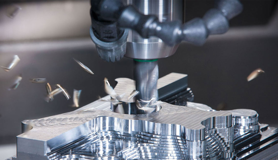
Subtractive
Remove material.
Milling · drilling · laser cutting
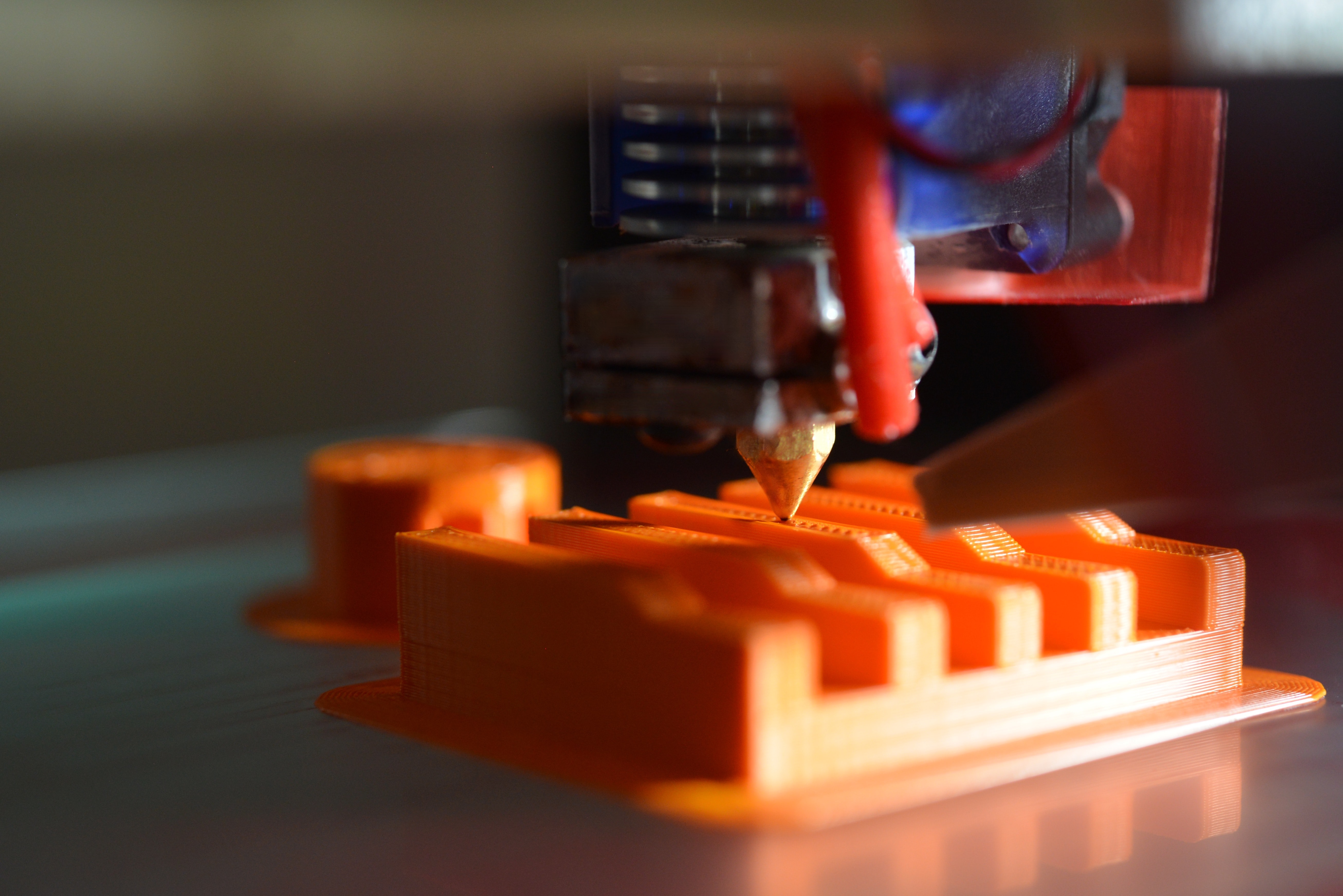
Additive
Build up material.
3D printing
What is FDM 3D printing?
A digital model becomes a physical part
one layer at a time.
- 01Feed
Filament enters the print head.
- 02Heat & deposit
A nozzle lays down softened plastic.
- 03Repeat
New layers bond to the layers below.

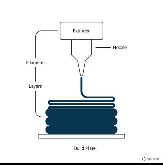
This talk focuses on filament printing: FDM / FFF.
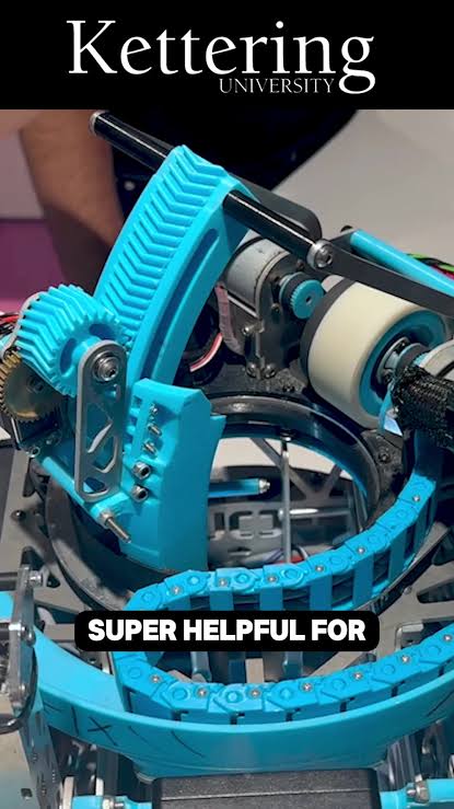
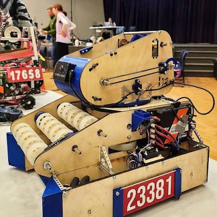
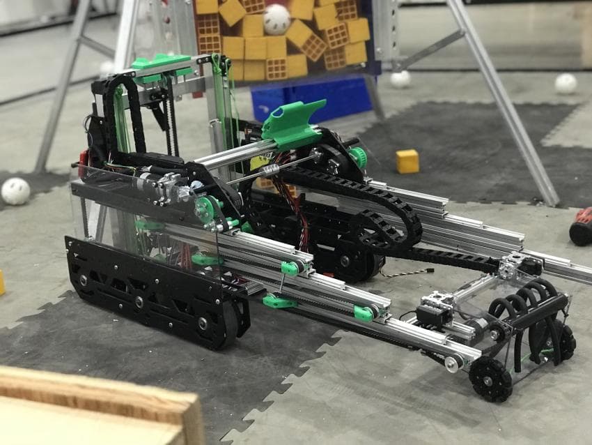
3D printing on an FTC robot
It’s everywhere!
What is rapid prototyping?
Each version builds on what you learned.
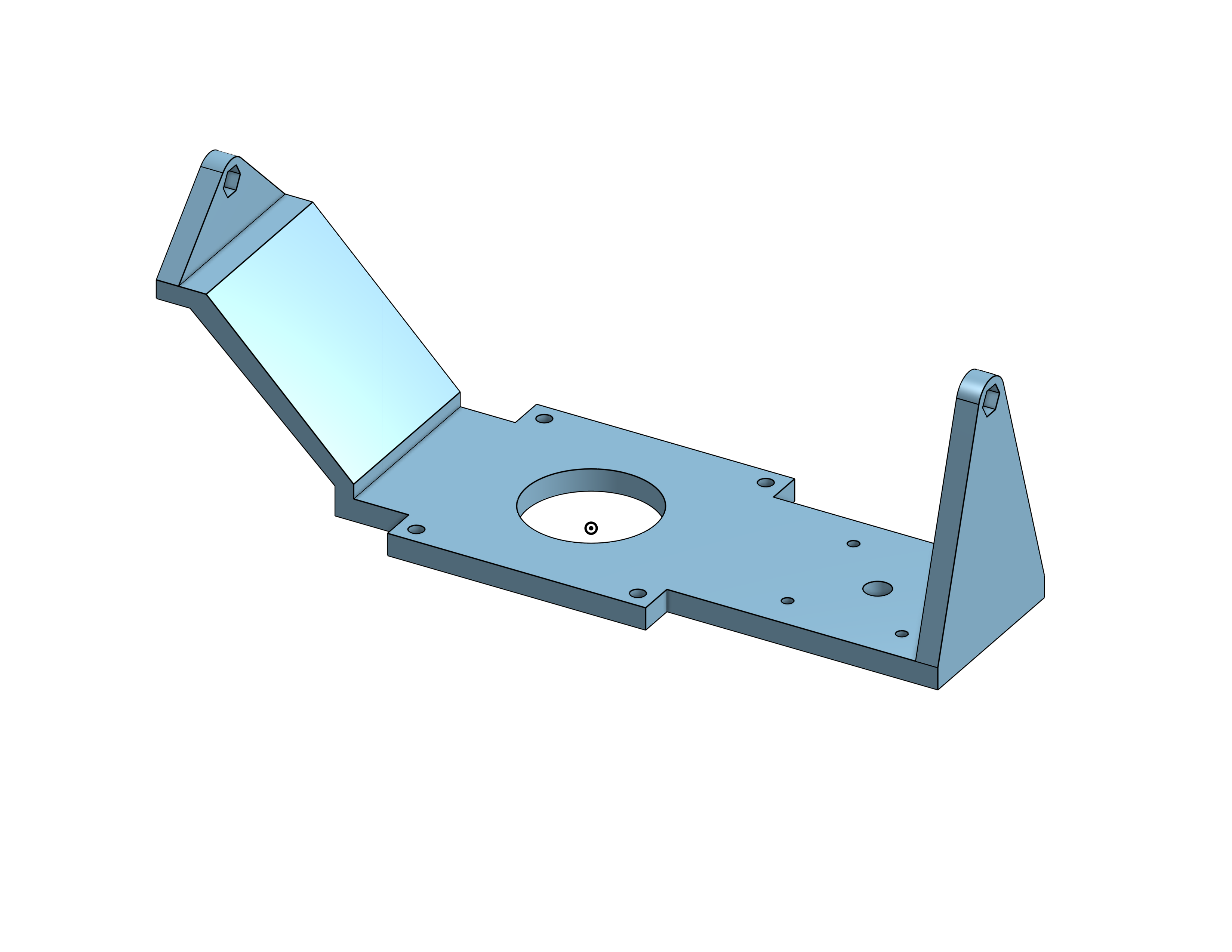
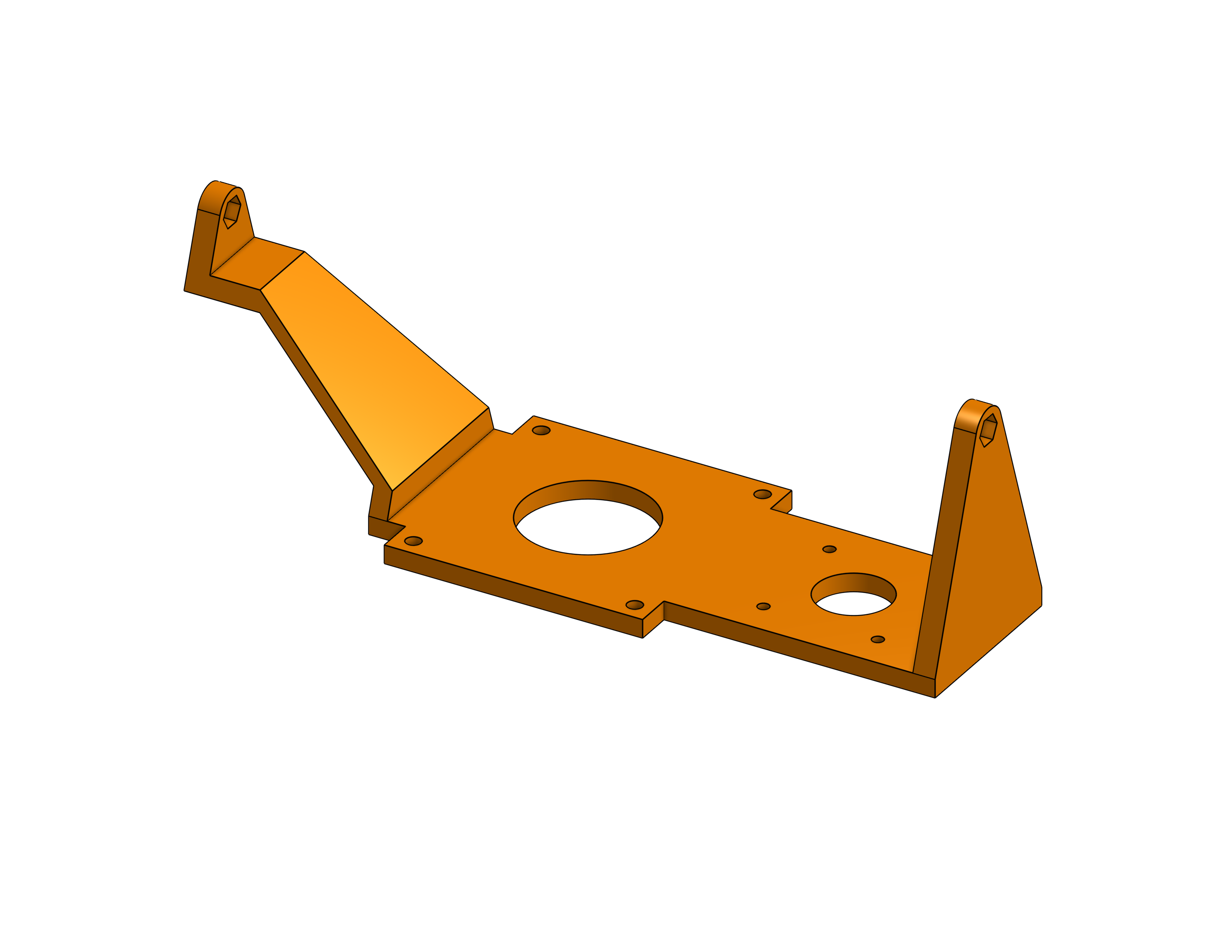
Design→Build→Test→Revise→Repeat
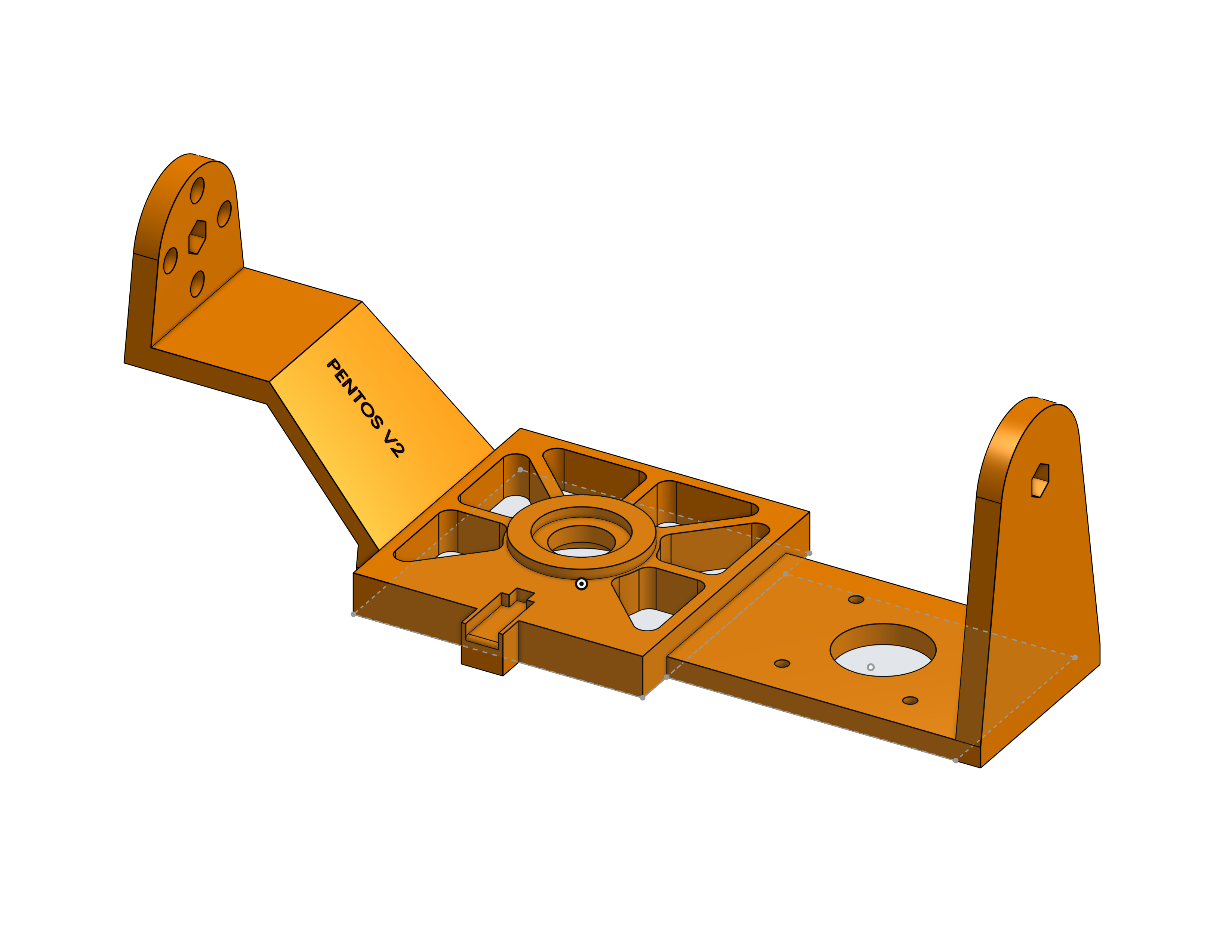
1. Print the smallest thing that answers your question
A small test piece can answer a big design question.
- Test only the critical section. Print the interface at its real dimensions before committing to the full part.
- Quick tip: print one layer, then cancel. Check the footprint and hole positions. Use a deeper sample for actual fit.
2. Orient your prints right!
Balance strength, support material, and surface finish.
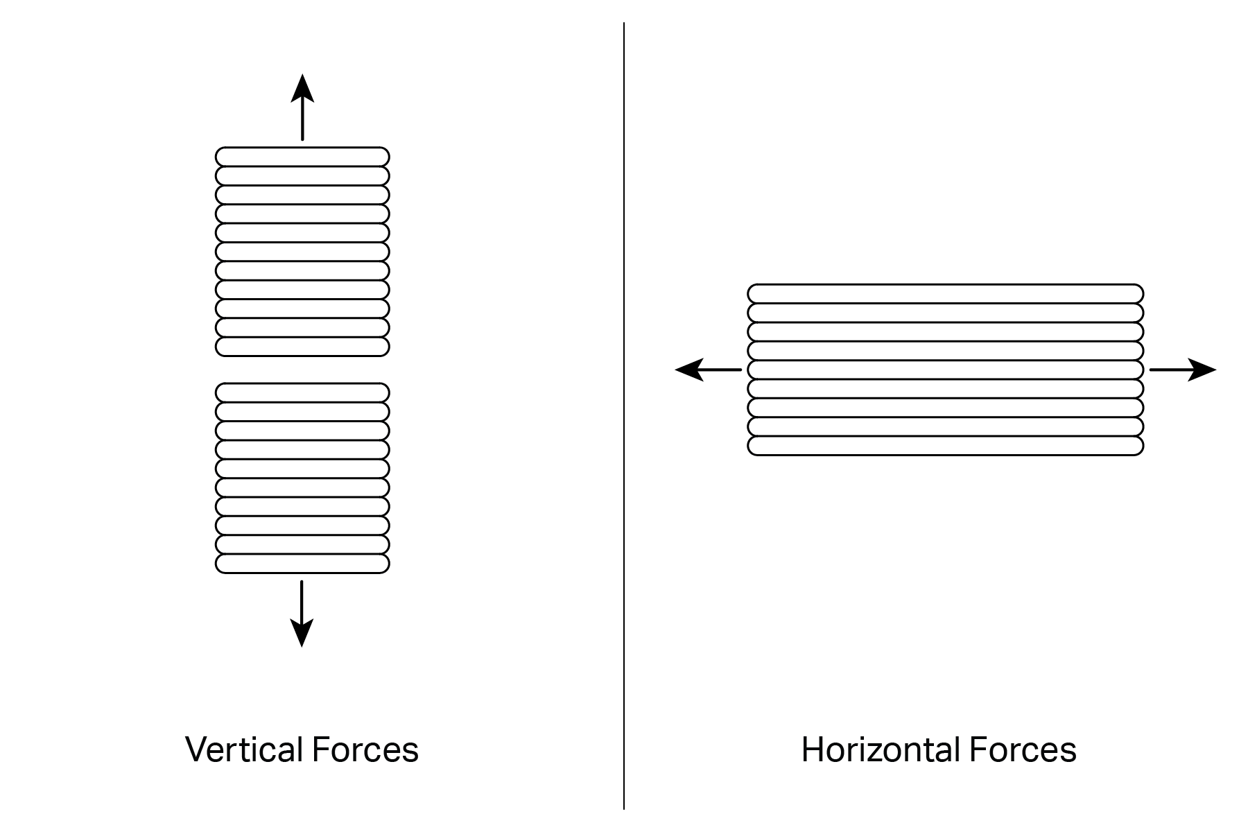
Respect the layers
Orient the part so working loads are less likely to pull layers apart.
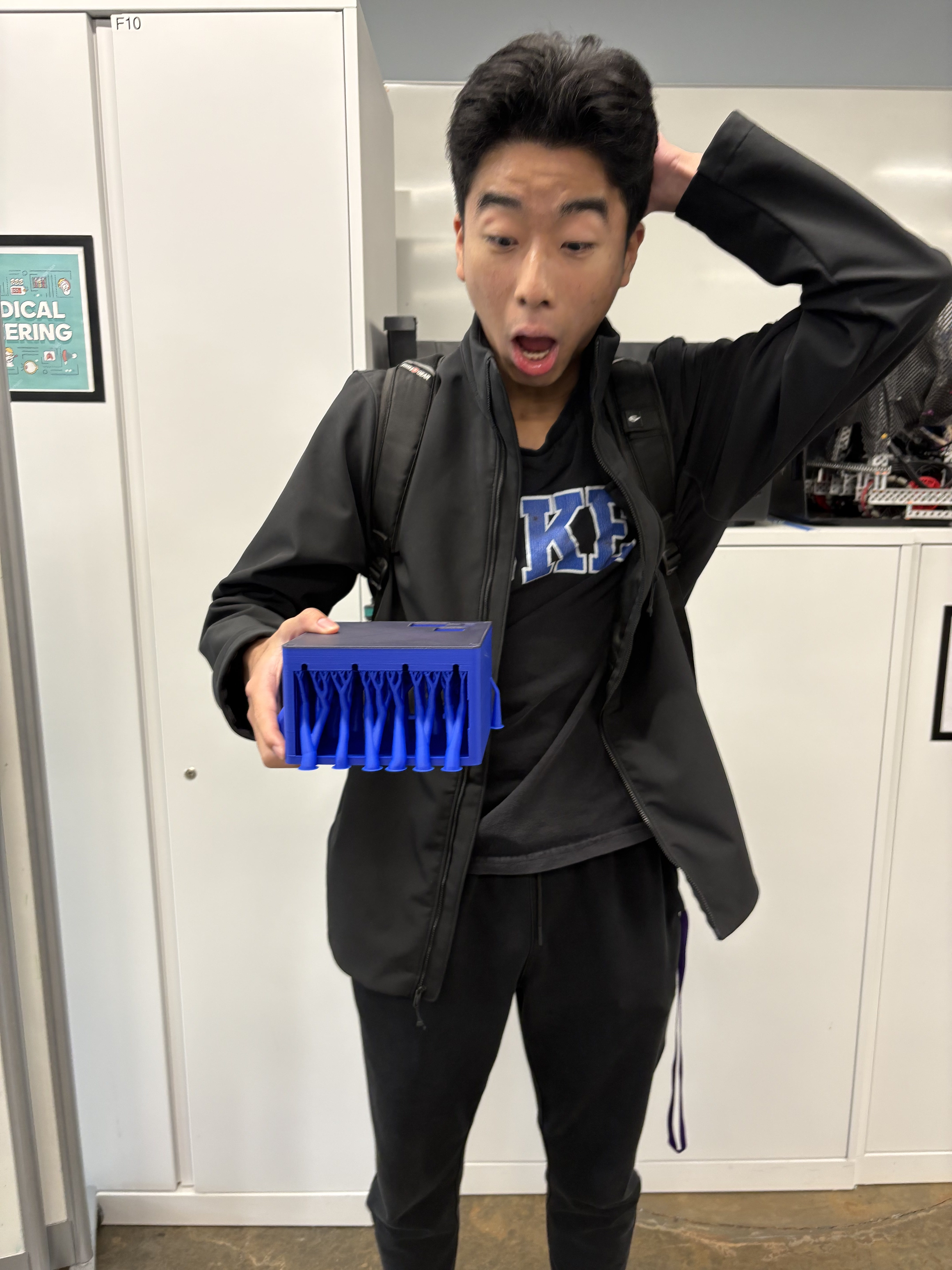
Minimize supports
Rotate to reduce unsupported overhangs. Check cleanup time and access.
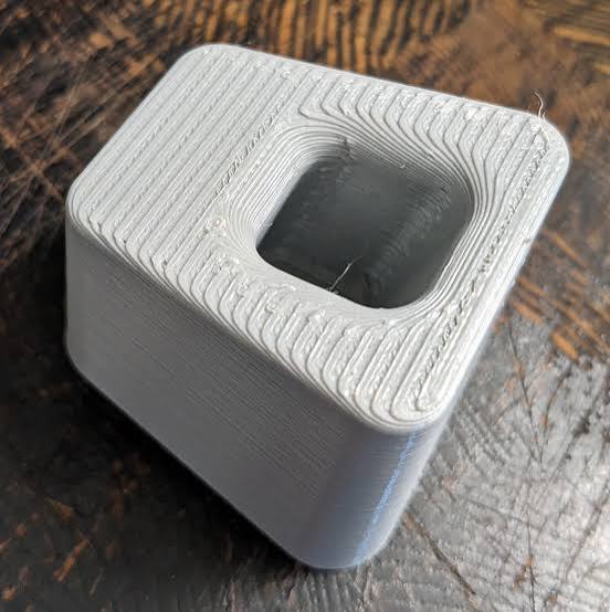
Choose the top face
Keep critical faces clear of support contact. Inspect top layers in the slicer.
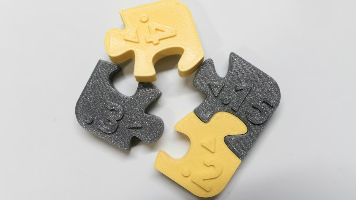
3. Measure real parts and test clearances
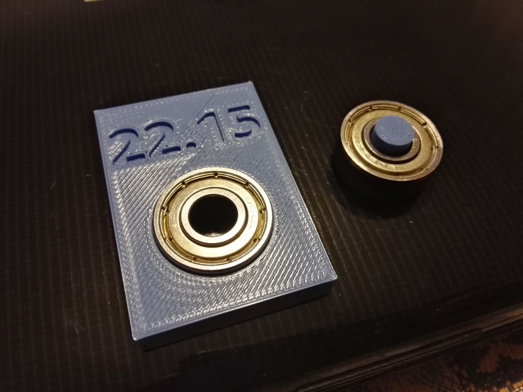
Rule of thumb: start with 0.2 mm clearance.
- Start around 0.2 mm. A starting point for a well-tuned 3D printer.
- Aim for a snug fit. Parts should go together without noticeable wiggle.
- If fit matters, test it. Print a small sample and adjust the clearance.
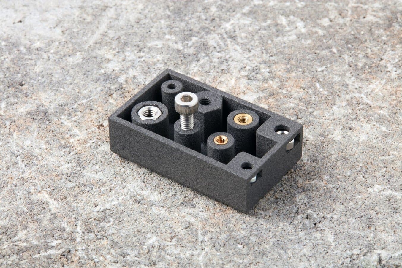
4. Three ways to screw into printed parts
Design the fastening method into the part.
- Captive nutTrap a metal nut in a shaped pocket so it cannot spin.
- Heat-set insertHeat a threaded insert into the plastic for reusable metal threads.
- Tapless / self-tappingUse a screw designed for plastic to form threads in a pilot hole.
5. Match the material and settings to the job
Bambu filament examples · values apply to these specific products
| Material comparison | PLA | PETG HF | TPU 95A HF | |
|---|---|---|---|---|
| Material properties | Impact strengthXY · kJ/m² | 26.6 | 31.5 | 123.2 |
| StiffnessBending modulus · XY · MPa | 2750 | 2050 | N/A in guide | |
| FTC applicationIllustrative uses | Rigid fit models | Functional mounts | Flexible contacts | |
| Print preparation | Nozzle temperature | 190–230 °C | 230–260 °C | 220–240 °C |
| Dry before use | Optional | Required | Required | |
| Enclosure | Optional | Optional | Optional | |
Layer heightDetail & print time
WallsShell & load paths
InfillInternal structure
Source: Bambu Filament Guide. Bars compare values within each row. Use the matching printer and filament profile.
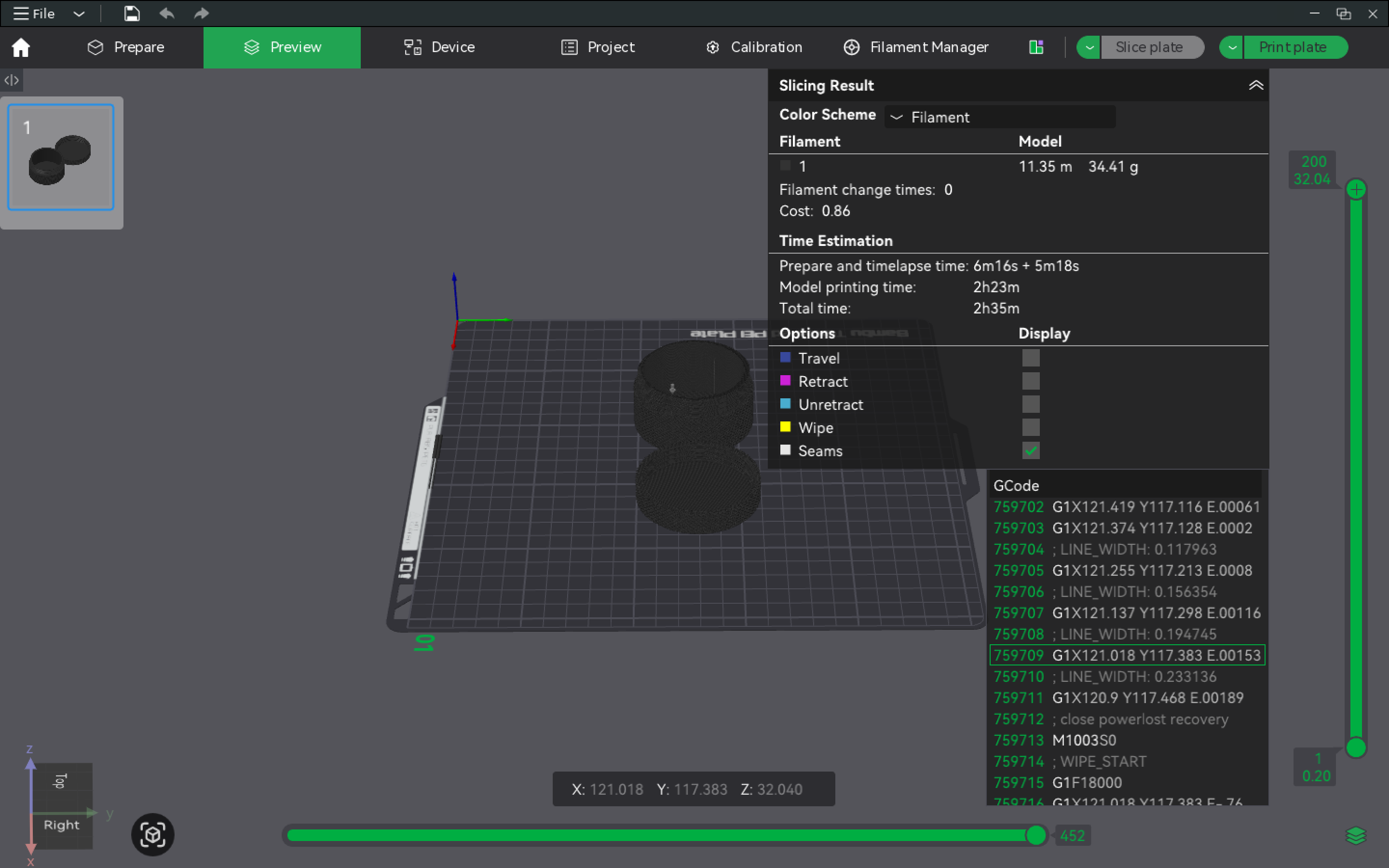
6. Inspect the sliced file before pressing print
The preview shows what the printer will actually build.
- Confirm the profile. Match the printer, nozzle, and filament.
- Scan the layers. Check for missing walls and unsupported starts.
- Inspect support contact. Check access for removal and surface finish.
- Review time and material. Compare orientations before increasing speed.
7. Use 3D printing to its strengths
Custom printed geometry. Metal where the structure needs it.
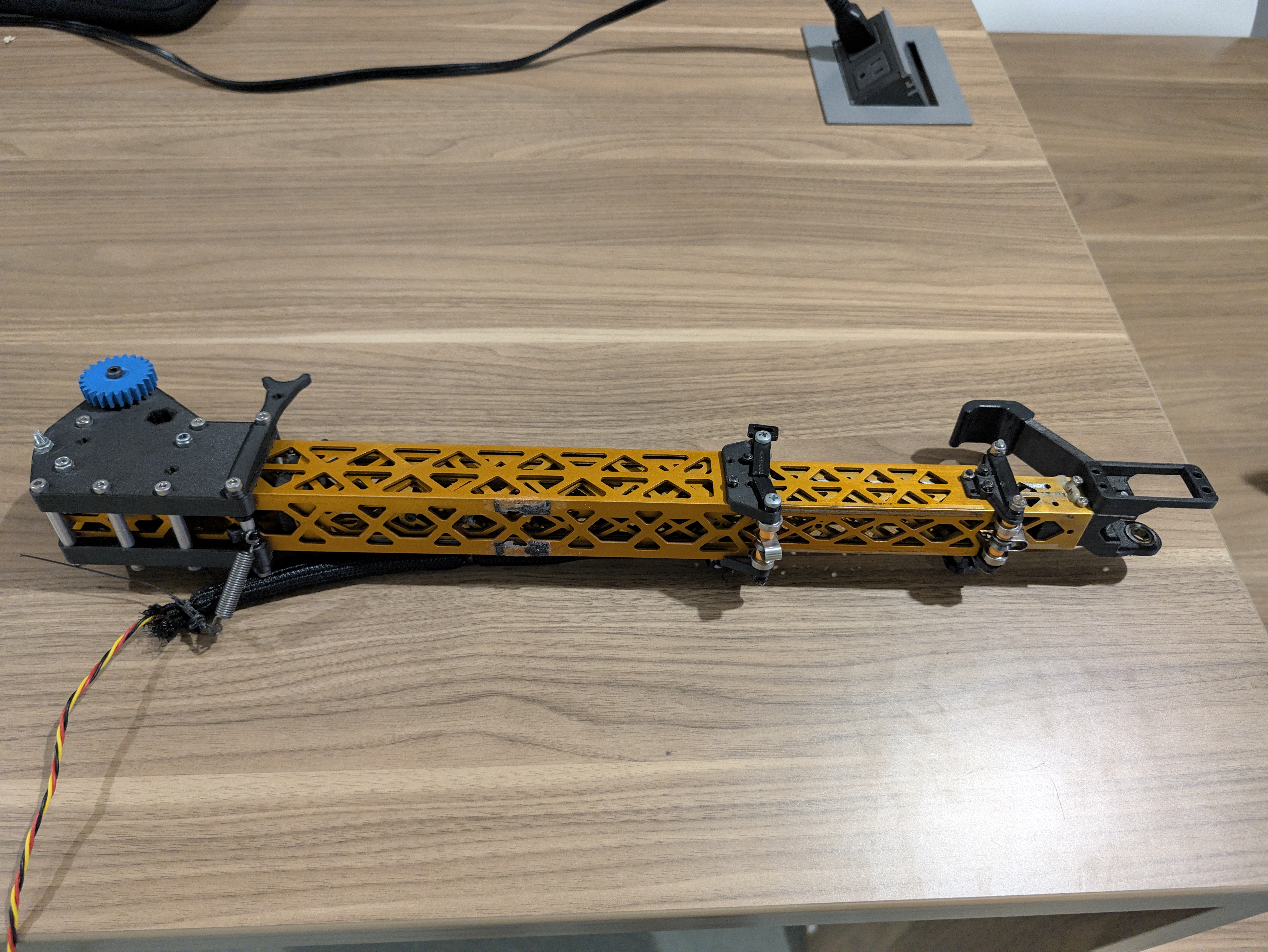
3D-printed partCustom shape and mounting features.
Metal tubeA structural member for the arm.
Try cardboard before committing to a print.Use cardboard, foam board, scrap wood, or tape to test size and motion. Print when custom geometry adds value.
What 3D printing can’t do
Practical limits of desktop FDM printing
Replace metal in every job
Loads, stiffness, wear, and heat may call for metal parts or standard hardware.
Print every shape unsupported
Overhangs may need supports, a different orientation, or a redesign.
Guarantee perfect fit and finish
Allow for process variation, layer lines, and cleanup. Test critical fits.
Prove that your design works
A finished print still needs testing on the robot under real conditions.
Thank you.
Questions?
 fdm.evankim.me